
Installation Instructions — 36" × 84" SPC 4‑Piece Alcove Shower Wall Panels
This guide applies to kits WPG4‑2 (Calacatta White Glossy), WPM4‑1 (Calacatta White Matte), WPG4‑4 (Bardiglio Grey), and WPG4‑6 (Calacatta Gold) — all 36" × 84". The kit is sized for a standard 36 in × 72 in × 36 in alcove(side × back × side); the panels cut easily to fit smaller alcoves — for example anywhere in the 30–36 in × 48–72 in × 30–36 in range (Section 5).
Welcome / Before You Begin
Thank you for choosing ProTier SPC shower wall panels. Before you begin:
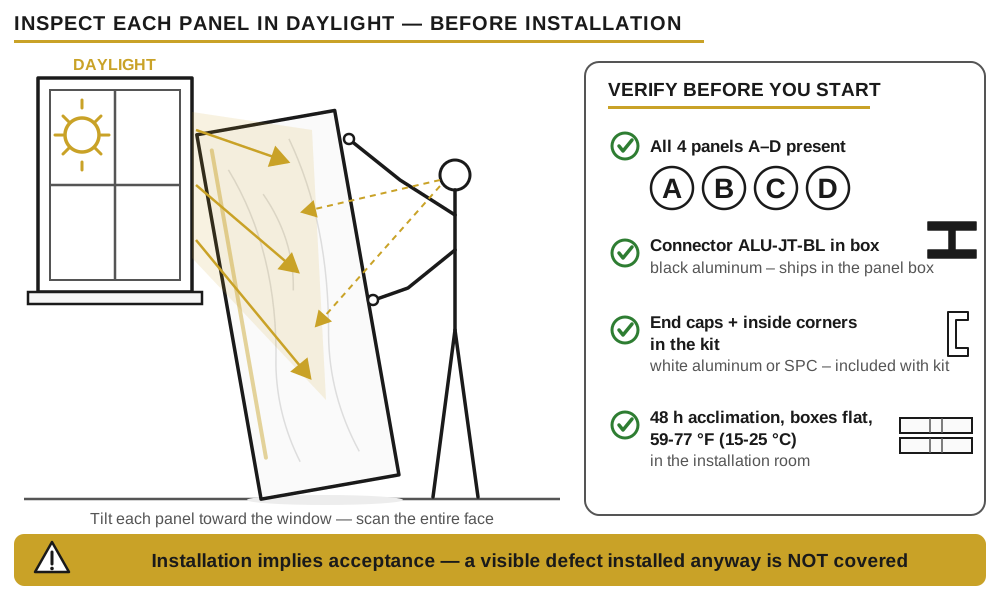
- Inspect every panel in daylight before installation — installation implies acceptance; installed panels with visible defects are not covered (Section 11).
- Acclimate the panels for 48 hours before installation: store the boxes flat in the installation room at 59–77 °F (15–25 °C), ideally 68 °F (20 °C).
- Finish all rough plumbing first and turn off the water supply.
- Plan 48 hours of dry time after installation (grout method: after grouting — Section 9); no showering during this period.
- Damaged or missing parts? Do not install — contact customer service first.
Safety Information
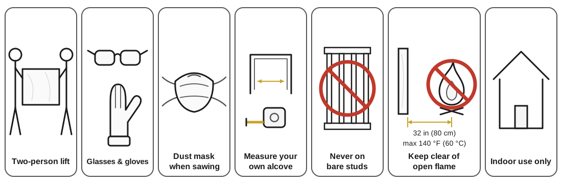
- Two-person lift recommended — panels are large and awkward.
- Wear safety glasses and gloves when cutting, drilling, and handling; add a dust mask when sawing.
- Remove faucet handles, trims, and the showerhead before installation.
- Always measure your own alcove — guide dimensions are for reference only.
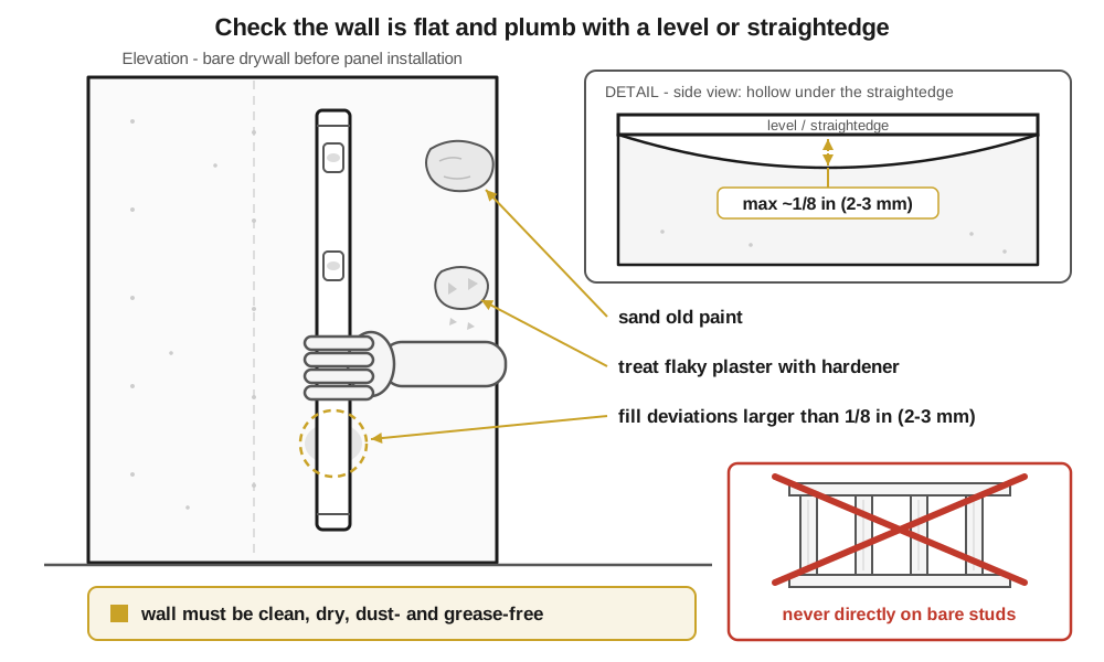
- Panels must never be installed directly onto bare studs — only over drywall or moisture-rated backer board.
- You are responsible for meeting local building and plumbing codes.
- Indoor use only. Never install behind an open-flame appliance; keep at least 32 in (80 cm) from a fireplace or stove.
- Maximum service temperature 140 °F (60 °C); thermal expansion approximately 0.07 mm/m/°C.
- Panels cut with a utility knife (score and snap), circular saw, jigsaw, or hole saw.
- Never mount heavy objects (grab bars, racks, mirrors) directly on the panels — see Section 9.
Choose Your Seam Method — DECISION GATE
3.1 — Identify your substrate
The panels install over either:
- WATERPROOF DRYWALL — moisture-rated backer board (cement board, foam backer board, or equivalent), or
- STANDARD DRYWALL / GYPROCK — ordinary, non-moisture-rated drywall.
Moisture-resistant "green board" gypsum is NOT waterproof drywall — for warranty purposes, treat it as standard drywall. If you are not certain which you have, treat it as standard drywall.
3.2 — Choose your seam-finishing method
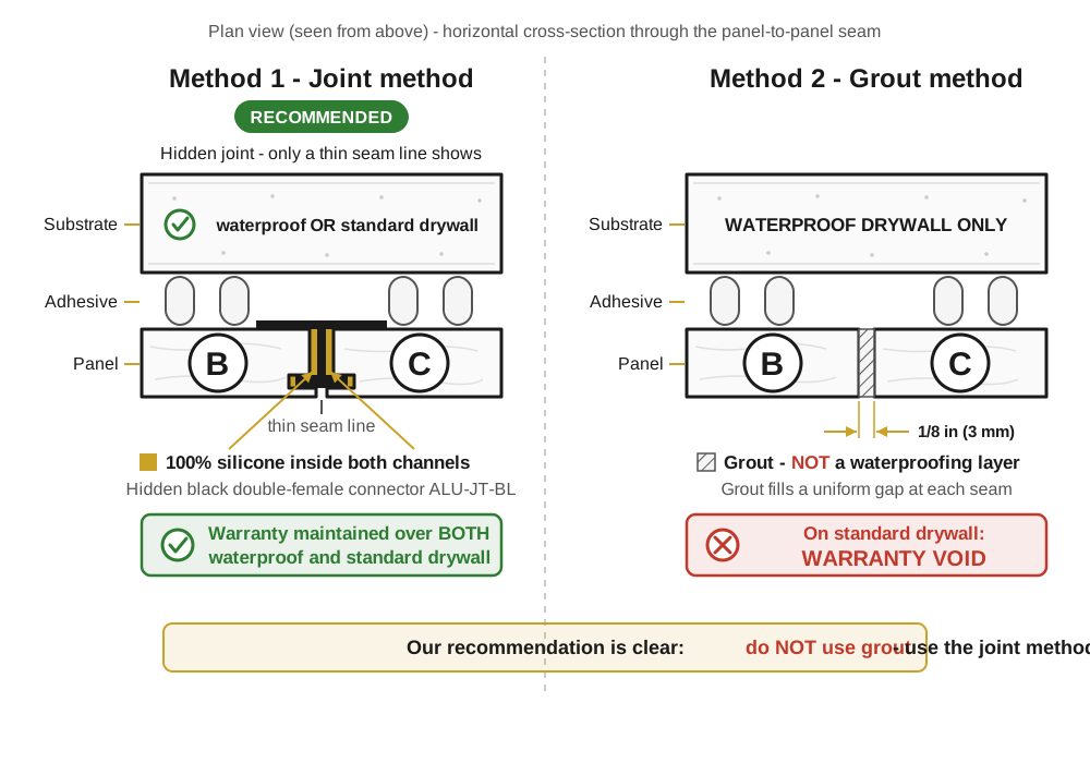
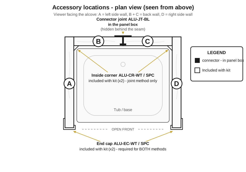
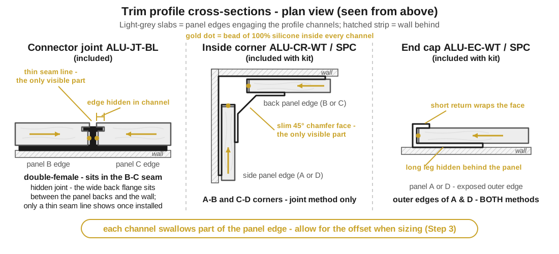
Method 1: Joint Method (RECOMMENDED). Silicone-sealed trim profiles finish the seams: the black aluminum connector joint in the middle seam between panels B and C, and aluminum or color-matched SPC inside-corner profiles in the two corner seams — all included with your kit (Section 5). Warranty maintained over BOTH waterproof drywall and standard drywall/gyprock.
Method 2: Grout Method. Grout fills a uniform gap at each seam instead of trim profiles. Permitted ONLY over waterproof (moisture-rated) drywall. Grout is not a waterproofing layer: over standard drywall the warranty is VOID — MGA does not guarantee waterproofing in that configuration. The end caps included with your kit are still required (Section 5).
3.3 — Confirm your combination is permitted
| Seam method | Waterproof drywall (moisture-rated backer) | Standard drywall / gyprock |
|---|---|---|
| Joint method (recommended) | ✔ Warranty maintained | ✔ Warranty maintained |
| Grout method | ✔ Warranty maintained | ✘ WARRANTY VOID |
Already in your kit (Section 5): the connector joint, two inside corners (joint method), and two end caps (both methods). The only things to buy are the adhesive, tape, silicone, and (grout method) grout — Section 4.
Tools & Materials
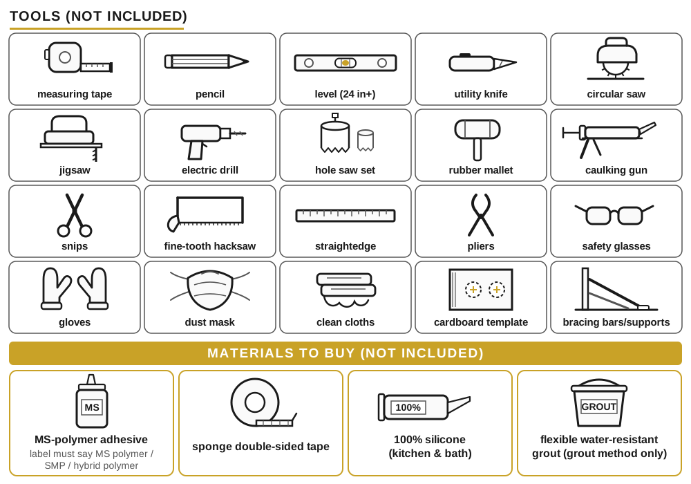
Tools (not included):measuring tape, pencil, level (24 in or longer), utility knife, circular saw or jigsaw, electric drill, hole saw set, rubber mallet, caulking gun, snips, fine-tooth hacksaw (for cutting trim profiles to length), straightedge, pliers, safety glasses, gloves, dust mask, clean cloths, cardboard (plumbing templates), and bars/wood supports for bracing during cure.
Materials you must buy (not included):
- High-strength MS-polymer construction adhesive (a single-component, polyurethane-style hybrid adhesive) from a reputable brand (e.g., Emfi High-Power), rated for prolonged moisture exposure. Only adhesives containing MS polymers may be used; any other adhesive voids the warranty.
Label test: the tube or technical data sheet must itself say "MS polymer," "silyl-modified polymer (SMP)," or "hybrid polymer."A label that says only "polyurethane," with no MS-polymer statement, does NOT qualify and voids the warranty. - Sponge double-sided construction tape (high-tack).
- 100% silicone sealant (kitchen & bath grade, mold-resistant).
- Grout method only: high-quality flexible, water-resistant grout.
What’s Included
In the panel box
| Item | Qty | SKU |
|---|---|---|
| SPC wall panels, labeled A, B, C, D | 4 | (part of kit) |
| Black Aluminum Panel Connector Joint — double-female (female-to-female) profile | 1 | ALU-JT-BL |
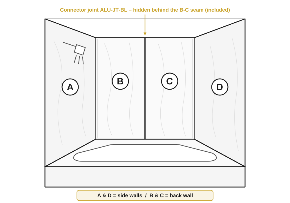
The connector joint goes in one place: the seam between panels B and C (middle of the back wall).
Panel layout: A and D are the side walls; B and C together form the back wall of the alcove.
Book-matched pattern: the panels are book-match designs — the pattern continues from panel to panel across the alcove, flowing through the centre B–C seam. Arrange them in the labeled A–B–C–D positions around the alcove, right side up — the panels are not interchangeable. (The gluing sequence is different and is set by Section 7: B first, then C, then A and D.)
Other alcove sizes: the kit is sized for a standard 36 in × 72 in × 36 in alcove (side × back × side). Smaller alcoves are easy because the panels cut cleanly — for example anywhere in the 30–36 in × 48–72 in × 30–36 in range. Final edge positions always come from the Step 3 dry-fit — hairline corner-side trims may be needed even at the standard size. When narrowing the back wall, trim B and C by equal amounts from their corner-side edges, never at the centre B–C seam — the factory centre edges, and the book-matched pattern, stay matched in the middle of the back wall. (Width trims keep the centre match; the pattern at a trimmed corner shifts by the amount cut.)
Also included with your kit
| Item | Qty | Used in | Where it goes |
|---|---|---|---|
| Inside Corner | 2 | Joint method only | A–B and C–D corners |
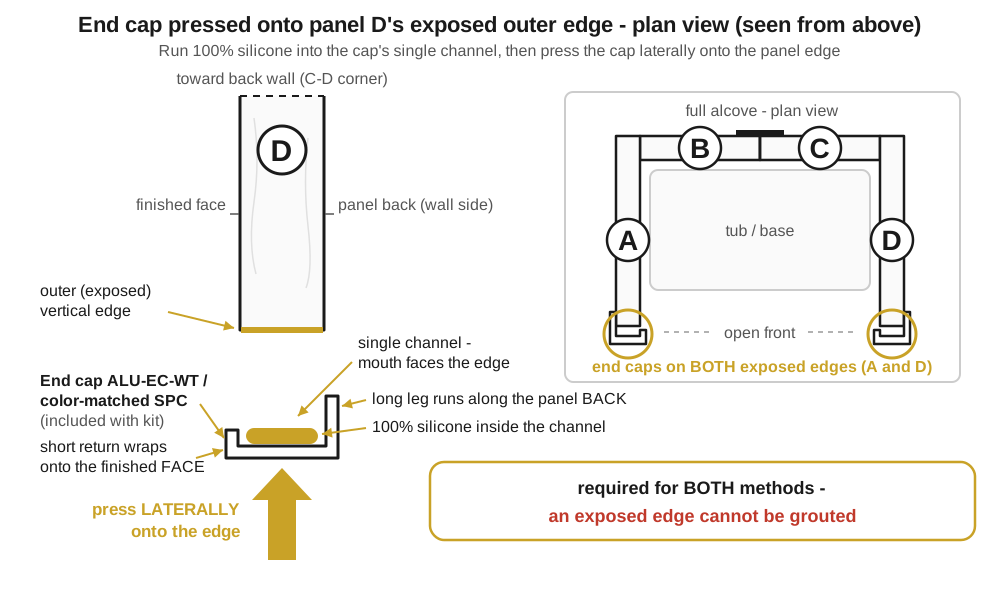
| End Cap | 2 | ALL installations — both methods | Exposed outer vertical edges of A and D |
The profile finish — white aluminum or color-matched SPC — depends on the kit version you purchased; the function is identical. (Calacatta White Glossy kits come with white aluminum or White Matte SPC profiles — no glossy SPC profile exists.)
Need a spare or replacement part? Contact customer service.
Wall Preparation
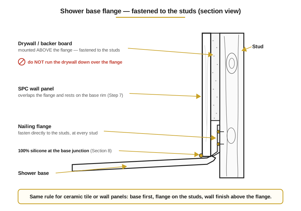
- Shower base or tub first — flange fastened to the studs. Whether the walls will be wall panels or ceramic tile, the base goes in first: set it level and fasten its nailing flange directly to the wall studs at every stud (predrill if the base manufacturer requires it; shim behind the flange to keep it straight). The drywall or backer board is then mounted above the flange — not over it — and fastened firmly to the studs. The panels later extend down in front of the flangeand rest on the base rim (Step 7); the base junction is sealed with silicone (Section 8). Renovating over already-finished walls? You can't see the flange, and you do not need to open the wall to check it: proceed as long as the base is solidly anchored (no movement or flex at the rim) and the wall near the base is sound, dry, and flat (items 2–7) — the panels overlap the base junction and the continuous silicone bead (Section 8) provides the seal. If the wall is loose, crumbling, or water-damaged near the base, repair that area first (Fig. 7).
- Confirm your wall type. Both waterproof (moisture-rated) and standard drywall/gyprock are acceptable — remember the seam-method rule (Section 3). Do not install directly onto bare studs.
- Check the wall is flat and plumb with a level or straightedge. Tolerance is about 1/8 in (2–3 mm); level larger deviations with filler or plaster first.
- Clean the wall. It must be flat, clean, dry, and free of dust, grease, soap residue, glue, wallpaper, and flaking paint or varnish.
- Sand old paint so the adhesive can grip.
- Treat flaky or powdery plaster with a hardener (plaster primer/consolidant) before installing.
- Never install on an untreated wet or damp wall. The wall must be fully dry.
Installation
STEP 1Verify and inspect
Confirm the four panels (A–D), the connector joint (ALU-JT-BL), the two end caps, and the two inside corners (used in the joint method) are present. Inspect each panel in daylight (Section 1); confirm 48 hours of acclimation.
STEP 2Check your height, then draw a level reference line
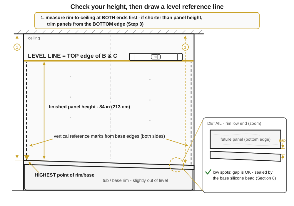
Measure from the highest point of the tub rim or shower base up to the ceiling, at both ends of the back wall. If the space is shorter than the panel height — 84 in (213 cm) — the panels must be trimmed from the BOTTOM edge during Step 3 (the factory top edge stays visible; the cut bottom edge is hidden at the base junction, which is siliconed in Section 8). Then, from the base's highest point, measure up your finished panel height and draw a level horizontal line across the back wall. This line marks the TOP edge of panels B and C. Mark vertical reference lines from the base edges on both sides.
STEP 3Dry-fit all four panels, with seam allowances
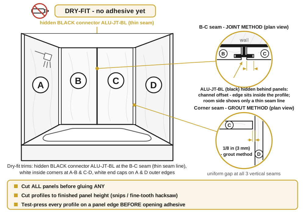
Stand each panel in place without adhesive: B and C on the back wall, A and D on the sides — in the labeled A–B–C–D positions, right side up. Confirm the book-matched pattern flows continuously across all three seams before making any cut (Section 5) — a panel that is swapped or upside down breaks the match. Check height and width with seam allowances before cutting anything:
- Joint method: dry-fit with the connector, corners, and end caps on the panel edges — each channel swallows part of the edge and offsets the panel from the adjacent wall (channel depth: profile packaging). Mark where each edge must land; you will glue to these marks.
- Grout method: include a uniform 1/8 in (3 mm) gap at all three vertical seams (or your grout manufacturer's stated joint width).
If the alcove is smaller, trim panels (circular saw, or score-and-snap with a utility knife) so cut edges land where a corner profile, a corner grout joint, or the siliconed base junction hides them. Height trims: bottom edge (Step 2). Width trims: narrow B and C by equal amounts, from their corner-side edges only — never cut the centre B–C edges, so the book-matched pattern stays matched in the middle of the back wall (Section 5); trim A and D from their corner-side edges too — A and D keep their factory front (end-cap) edges. All width cuts then land in the corners, hidden inside the corner profiles (joint method) or the corner grout joints (grout method).
Joint method, also during dry-fit:
- Cut each trim profile (connector, inside corners, end caps) to your finished panel height with snips or a fine-tooth hacksaw.
- Test-press each profile onto a panel edge while the panel is held against the wall to confirm it seats fully — do this before any adhesive is opened, and decide now whether you will pre-fit the profiles on panel B's edges before gluing (Step 7) or press them on afterward.
STEP 4Mark plumbing cutouts
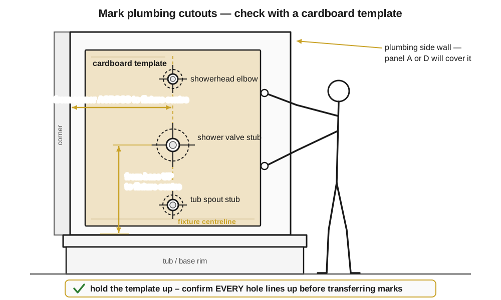
On the panel covering your plumbing (usually a side panel), measure from the base and from the corner to each fixture centre. Make a cardboard template with the holes marked, hold it against the wall, and confirm every hole lines up.
STEP 5Drill the holes FROM THE BACK of the panel
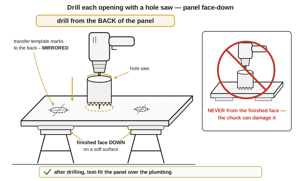
Transfer the template marks to the back of the panel (mirrored). Drill each opening with a correctly sized hole saw from the back of the panel — the drill chuck can damage the finished face. Test-fit the panel over the plumbing.
STEP 6Apply tape and adhesive (one panel at a time)
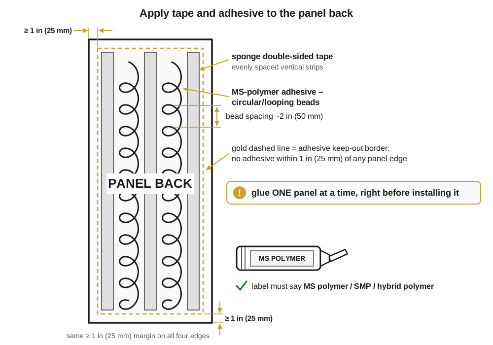
Glue one panel at a time, immediately before installing it. Wipe the panel back and the wall clean and let dry, then:
- Apply sponge double-sided construction tape in evenly spaced vertical strips on the panel back.
- Between the strips, apply beads of MS-polymer construction adhesive in a circular/looping pattern.
- Keep all adhesive no closer than 1 in (25 mm) to the panel edges, with beads spaced about 2 in (50 mm) apart.
STEP 7Install panel B (back wall, first half)
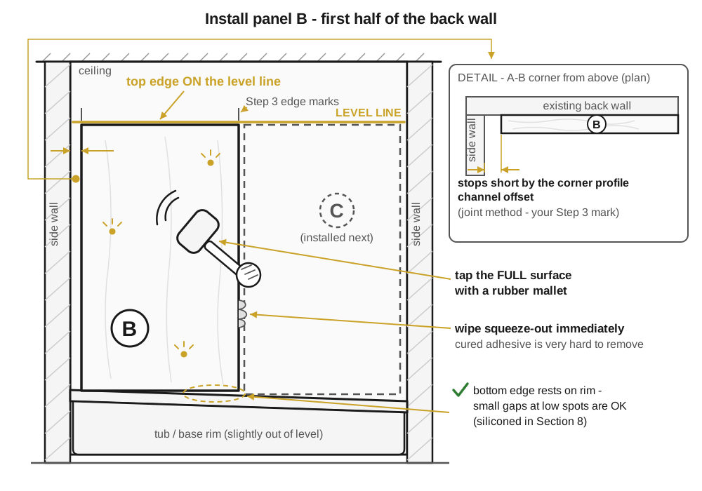
Apply tape and adhesive to panel B (Step 6 pattern). Align B's top edge with the level line, matching your Step 3 edge marks; the bottom edge rests on the tub rim or base. If the rim is out of level, small gaps under the panel at low spots are normal — the continuous silicone bead at the base junction (Section 8) seals them. Joint method: B's corner-side edge stops short of the side wall by the corner profile's channel offset (your Step 3 mark). Press B firmly onto the wall and tap the full surface with a rubber mallet. Wipe off squeeze-out immediately — cured adhesive is very hard to remove.
STEP 8Fit the connector joint, then panel C
Joint method:
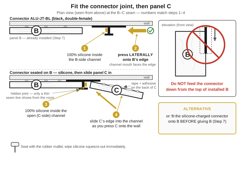
- Run a bead of 100% silicone inside the connector channel that will receive panel B's edge.
- Press the connector (ALU-JT-BL) laterally onto installed panel B's open edge, channel opening facing the edge, until fully seated along its length — or fit the silicone-charged connector onto B's edge before gluing B (Step 7).
- Run a bead of 100% silicone inside the open channel (panel C's side).
- Apply tape and adhesive to panel C (Step 6 pattern), then slide C's edge into the open channel as you press C onto the wall. Seat with the mallet; wipe squeeze-out.
Grout method (waterproof drywall only): No seam profiles are used. Apply tape and adhesive to panel C (Step 6 pattern)and install it leaving the 1/8 in (3 mm) gap from Step 3 (grouted in Step 12). Seat with the mallet; wipe squeeze-out.
STEP 9Inside corners, then side panels A and D
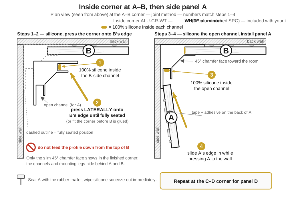
Joint method: At the A–B corner, run silicone inside the corner-profile channel that will receive panel B's edge, press the inside corner (ALU-CR-WT or color-matched SPC) laterally onto B's edge until fully seated (or fit it before that panel is glued), then run silicone inside the open channel. Apply tape and adhesive to panel A (Step 6 pattern), slide its edge into the open channel, press, and seat with the mallet. Repeat at the C–D corner for panel D.
Grout method:Apply tape and adhesive to panel A (Step 6 pattern); install it with the same 1/8 in (3 mm) corner gap. Repeat for panel D.
STEP 10End caps on the exposed edges (both methods)
Finish the exposed outer vertical edges of panels A and D with end caps (ALU-EC-WT or color-matched SPC) — required for BOTH methods; an exposed edge cannot be grouted. Run silicone into each end cap's single channel and press it laterally onto the edge.
STEP 11Apply curing pressure
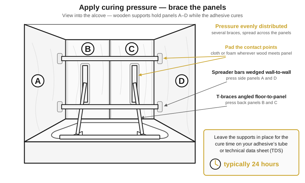
Brace each panel with bars or wooden supports, pressure evenly distributed, while the adhesive cures. Leave the supports in place for the cure time stated on your adhesive's tube or technical data sheet — typically 24 hours — before removing them and completing the sealing inspection (Section 8).
STEP 12Grout method only: grout the seams
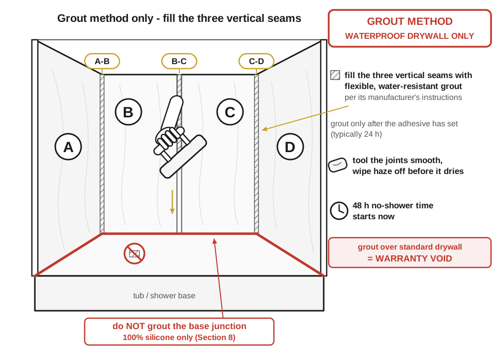
Wait for the adhesive to set (typically 24 hours), then fill the three vertical seams (A–B, B–C, C–D) with flexible, water-resistant grout per its manufacturer's instructions. Do NOT grout the junction where the panels meet the tub or shower base — that joint must be sealed with 100% silicone (Section 8). Tool the joints smooth and wipe haze off before it dries. Your no-shower dry time starts now (Section 9). Reminder: only over waterproof drywall.
Sealing — This Is What Makes It Waterproof
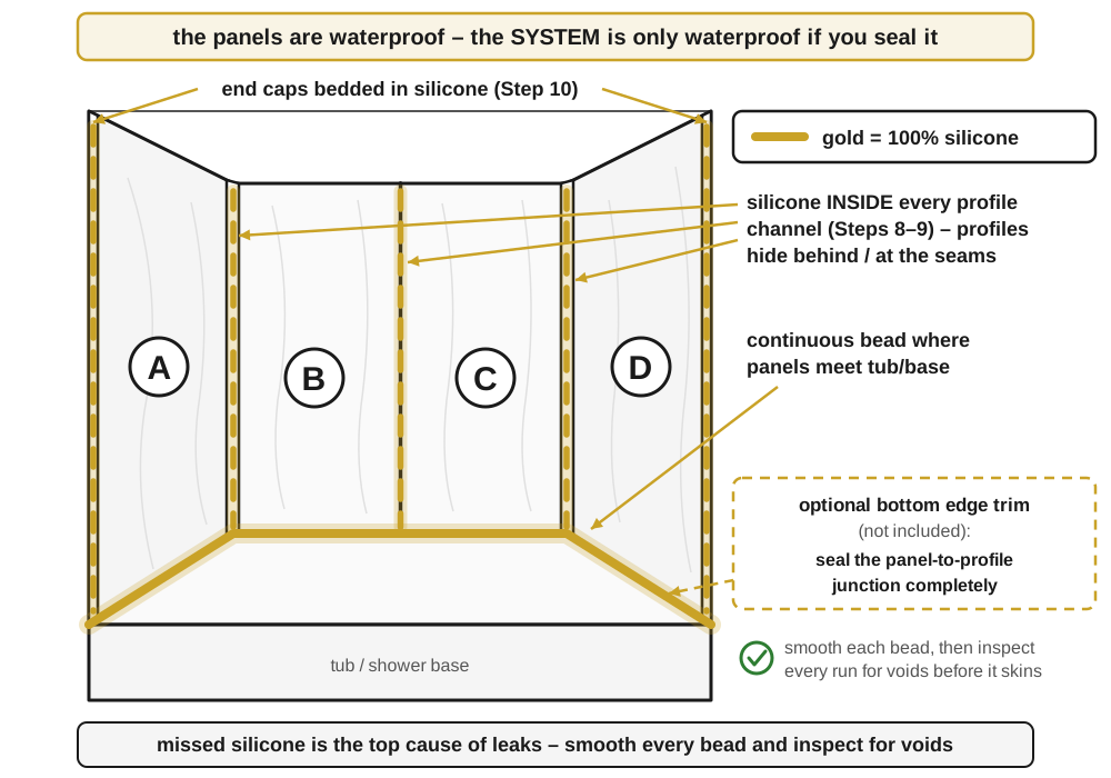
The panels are waterproof; the system is only waterproof if you seal it. Apply 100% silicone at:
- Where the panels meet the tub or shower base — a continuous bead along the entire bottom edge of all four panels.
- Inside the joint profiles at every splice connection. Joint method: you siliconed both channels of the connector and corner profiles during Steps 8–9 and bedded each end cap in silicone (Step 10) — inspect every profile and fill any gaps. Grout method: only the end caps (Step 10) apply; verify their silicone bedding is continuous.
- If you use an optional bottom edge trim profile (not included), seal the panel-to-profile junction completely.
Smooth each bead and inspect for voids — missed silicone is the top cause of leaks.
After Installation
- Keep the room dry for 48 hours after installation — no showering while adhesive and silicone cure. Grout method: count the 48 hours from grouting (Step 12), or the grout manufacturer's full cure time if longer.
- Remove residue with a soft cloth; for stubborn smears use the adhesive manufacturer's recommended cleaner — never solvents (Section 10).
- Reinstall faucet trim and the showerhead, restore the water supply, and check every connection for leaks.
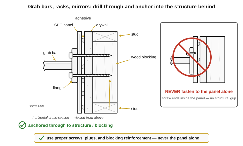
- Mounting heavy objects (grab bars, racks, mirrors): never fasten them to the panels alone. Drill through the panel and anchor into the structure / load-bearing wall behind with proper screws, plugs, and blocking reinforcement.
Care & Maintenance
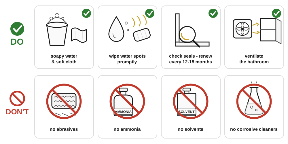
- Clean with soapy water and a soft cloth.
- Never use abrasives, ammonia, solvents, or corrosive cleaners — they dull or damage the finish.
- Wipe off water spots promptly to prevent limescale.
- Check your silicone seals regularly. Renew any bead that cracks or pulls away (typically every 12–18 months).
- Ventilate the bathroom (exhaust fan or open window) to limit mildew.
Warranty
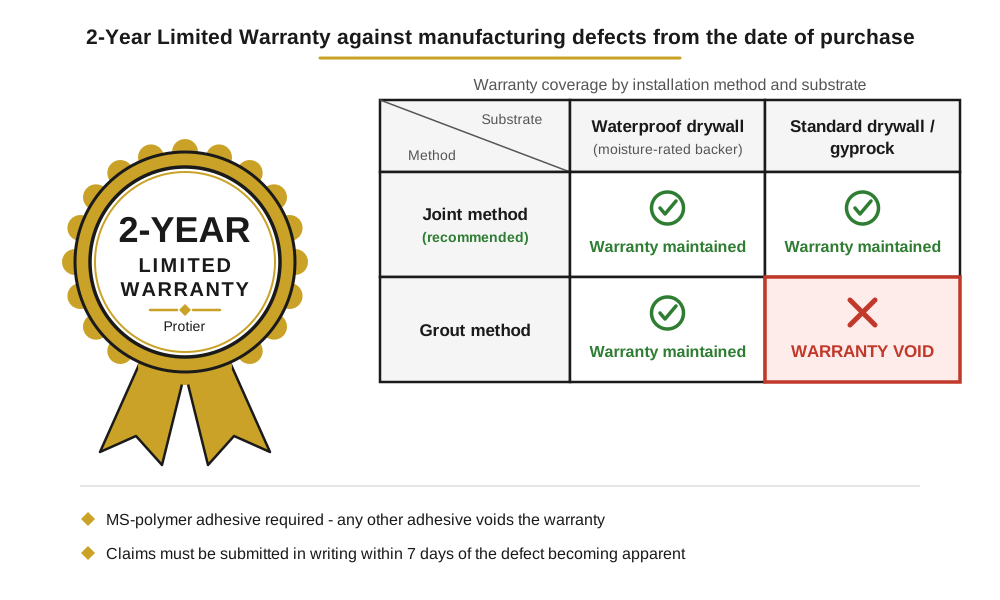
2-Year Limited Warranty. ProTier SPC shower wall panels are warranted against manufacturing defects for two (2) years from the date of purchase.
What is covered: Replacement of the verified defective panel with wall material of equivalent or similar quality available at the time of the claim.
What is not covered:
- Removal or reinstallation costs.
- Products not sold in their original packaging; promotional/clearance items are excluded.
- Appearance or color change from normal aging.
- Circumstantial damage (fire, water events, etc.).
- Any installation using an adhesive that does not contain MS polymers.
- Grout-method installations over standard (non-waterproof) drywall (Section 3) — MGA does not guarantee waterproofing in that configuration.
- Damage from transport or improper handling.
- Outdoor use. These panels are for indoor use only.
Installation implies acceptance. Inspect every panel in daylight before installation. A panel with a visible defect that is installed anyway is excluded; defects visible before installation will not be considered afterward.
Making a claim: Claims must be submitted in writing within 7 days of the defect becoming apparent, with complete details and supporting evidence (photos, batch numbers, proof of purchase). We reserve the right to inspect the affected product.
This warranty applies only when the product is installed and maintained per this guide, without prejudice to statutory consumer rights under Canadian law. Joint waterproofing is the installer's responsibility; the panels themselves are warranted waterproof.
Questions? Contact ProTier customer service before installing. Keep this guide and your proof of purchase.
Questions about your install?
Our team can help — we reply within one business day.